
PVC High Speed Roll Up Door Installation Guide – Part 1: From Customer Measurements to Installation Drawings
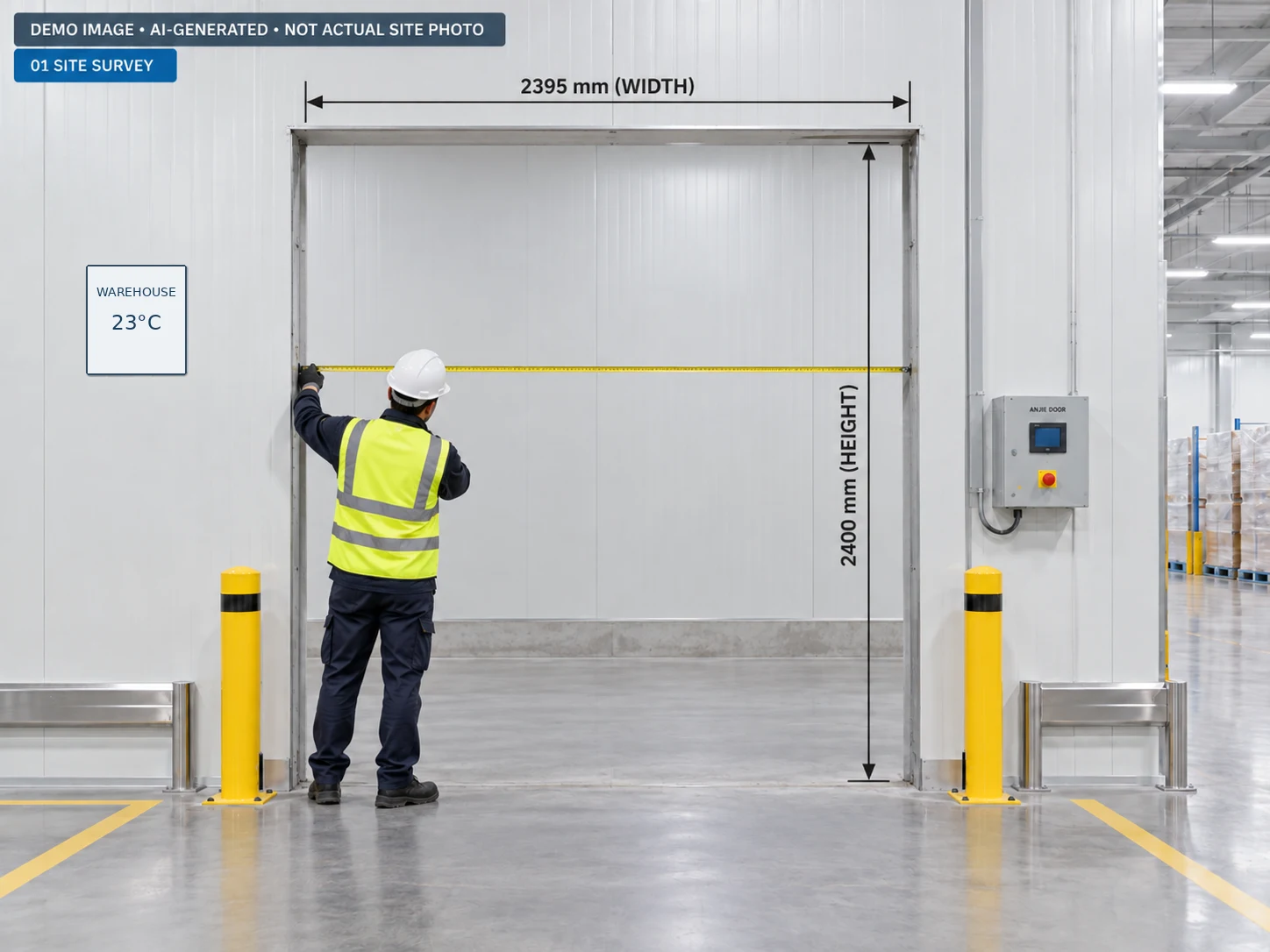
Figure 1. Measurement demonstration, not an actual site photograph. The dimensions reproduce the customer-reported brief; perspective, surrounding fixtures and visible equipment are illustrative. Site measurements remain necessary.
A warehouse project planning example with a 2395 × 2400 mm opening.
A PVC high speed roll up door installation starts well before the door arrives on site. The first question is not where to drill the fixing holes, but whether the proposed door, the building opening and the intended traffic have been coordinated correctly.
In this first article, we use a documented ANJIE DOOR project brief to explain the preparation process: collecting customer requirements, checking dimensions, choosing the mounting arrangement and preparing an installation coordination drawing. Part 2 will cover an illustrative on-site installation and commissioning sequence.
About this case: The opening dimensions and operating requirements below come from project coordination record AJ-WH-2395-2400, Rev P1. Installation completion has not been verified. Photographic-style illustrations are demonstration images, not actual customer-site photographs. The drawing is a planning illustration, not a released construction drawing. [1]
1. Start with the application, not just the opening size
The project brief concerns an internal connection between a warehouse at approximately 23°C and a goods corridor at approximately 30°C. The reported opening is 2395 mm wide × 2400 mm high, with forklifts and hand trolleys passing through approximately 10 times per hour. [1]
| Project item | Recorded requirement or selection |
|---|---|
| Installation location | Internal warehouse-to-corridor opening |
| Existing opening | 2395 mm W × 2400 mm H; site remeasurement required |
| Temperatures | Warehouse: 23°C; corridor: 30°C |
| Traffic | Forklifts and hand trolleys |
| Reported activity | Approximately 10 movements per hour |
| Selected door | Sealed self-repairing PVC high-speed door, standard curtain |
| Optional feature | Lower vision window; dimensions and inclusion to be confirmed |
| Requested operation | Activation from both sides and automatic closing |
| Requested protection | Safety light curtain and necessary presence detection |
| Power-failure requirement | Manual opening; method and supplied equipment to be confirmed |
This brief gives us a starting point, not a manufacturing specification. In particular, “10 movements per hour” should be clarified: does one movement mean one passage, one opening command or a complete opening-and-closing cycle? Our proposed follow-up also asks for the busiest short period, operating hours and any traffic that waits in the doorway.
For this case, we describe the application as a temperature-controlled warehouse passage, not a freezer-room entrance. The project record does not establish a cold-storage insulation rating. [1]
2. Collect measurements that the manufacturer can actually use
A customer’s message saying “the opening is 2395 × 2400 mm” is useful, but it does not describe the available installation space or the finished clear passage. The next step is a consistent survey record.
For this project, we recommend the following measurement checklist. Record actual readings and identify where they were taken; do not average away a narrow point or substitute an estimated size.
| Survey item | What to record |
|---|---|
| Opening width | Readings at the top, middle and bottom |
| Opening height | Readings at the left, centre and right, referenced to finished floor level |
| Opening geometry | Both diagonals, visible distortion and the condition of the jambs and lintel |
| Available headroom | Space above the opening to the lowest relevant obstruction |
| Available side room | Left and right clearances measured separately |
| Front clearance | Available projection and space for cover removal, tools and servicing |
| Wall and support | Wall thickness, supporting structure and proposed fixing locations |
| Floor | Slope, high points, thresholds, drains and planned floor finishes |
Checking the opening against the supplied door, identifying obstructions, verifying level bearing surfaces and establishing secure anchorage are also explicit preparation checks in manufacturer installation guidance. The actual ANJIE model instructions must determine the installation tolerances and fixing method. [2]
Keep the floor reference consistent
Use finished floor level (FFL) as the agreed height reference. Our survey form should ask whether the floor finish is complete and whether a threshold or ramp will be added. A reading from an unfinished slab is not the same reference as a reading from the final driving surface.
The proposed drawing must identify that reference explicitly. In this case, the original coordination record already uses FFL and leaves the installed clear height unconfirmed. [1]
3. Request a useful set of site photographs
Dimensions and photographs answer different questions. The proposed photo brief for this project is a straight-on view from each side, an angled view showing the wall depth, close-ups of the lintel and both jambs, and a wider view showing the ceiling, floor and traffic approaches.
Ask the customer to identify the preferred installation side, possible motor position, nearby electrical supply and anything that must remain accessible. Pipes, cable trays, lighting, adjacent doors and protective barriers should be visible rather than cropped out.
These photographs are a coordination aid. They cannot certify a hidden wall structure, identify every buried service or prove that an anchor location has sufficient capacity. Manufacturer guidance specifically requires the suitability of lightweight and insulated-panel walls to be assessed before installation. [3]
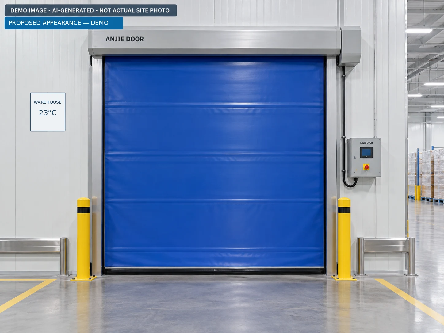
For the demonstration images in this series, the white wall panels, blue curtain, control box and bollards are visual examples—not verified details of the customer’s building or final order.
4. Check the mounting arrangement and the real clear passage
The current coordination drawing explores a face-mounted arrangement, with the side equipment outside the opening and the roll housing above it. This is a design assumption; the installation side and the equipment dimensions remain to be confirmed. [1]
Face mounting should not be confused with mounting the door inside the opening. The relevant question is how much of the existing aperture remains usable after every installed component is considered.
For a simple inside-mounted arrangement, the dimensional relationship can be expressed as:
Installed clear width = verified opening width − total left and right intrusion
Installed clear height = verified opening height − total effective vertical intrusion
These are coordination relationships, not ready-to-use manufacturing dimensions. The manufacturer must determine the limiting clear passage, including any guides, bottom edge, curtain position or other components that remain within it.
For this project, the distinction is essential:
- W0 / H0: customer-reported existing opening, 2395 / 2400 mm.
- Wc / Hc: usable opening after installation, both TBC.
The source drawing explicitly does not promise a finished clear opening of 2395 × 2400 mm. [1]
Our traffic review should therefore request the forklift and load envelope—not just the vehicle width. Record the widest load, the highest travel configuration, pallet overhang and the approach arrangement. The competent project team can then assess the required operating margins rather than treating the nominal doorway size as permission for passage.
5. Record the selected curtain and optional window correctly
The documented selection is a standard sealed self-repairing PVC high-speed door, without a multilayer insulation upgrade. ANJIE’s corresponding zipper-door product page describes automatic curtain reinsertion following disengagement; that feature does not make the door collision-proof or remove the need for a site-specific safety design. [1, 4]
For this planning example, the emphasis is on coordinating the selected door with the internal passage. The approximately 7°C temperature difference follows from the reported 23°C and 30°C conditions, but it is not, by itself, a verified thermal-performance specification.
Before making a thermal claim, our proposed follow-up would ask about humidity, air-pressure differences, how long the opening remains exposed and the customer’s temperature-control target. The case file provides no tested U-value, air-leakage rating or measured energy-saving result, so none is claimed here. [1]
Treat the lower vision window as an option
The case includes an optional lower vision window, not a confirmed standard inclusion. Its width, height, lower-edge elevation, material, compatibility with the self-repairing curtain and commercial inclusion remain to be agreed. The final drawing should state these rather than copying a window position from a demonstration image. [1]
6. Separate opening commands from safety protection
The customer requested activation from both sides, automatic closing, a safety light curtain, necessary presence detection and manual operation during a power failure. These are recorded requirements, not proof that a particular sensor package has been supplied. [1]
Activation tells the door that access is requested. Protective detection helps the control system respond to an occupied or hazardous area. A microwave motion sensor intended for opening a door should not automatically be treated as a stationary-presence safety device; the functions must be confirmed for the selected equipment. [5]
For this project, our proposed control review asks what happens when a trolley stops in the doorway, when traffic approaches from the opposite side, and when a protective device detects a fault. It should also establish the closing sequence and the conditions for a safe restart.
Safety depends on the assembled system, including compatible components, wiring, controller behaviour, detection coverage and site-specific risks—not merely the number of sensors listed in a quotation. Competent personnel must assess the final arrangement. [6]
The power-failure provision also needs an explicit description: the supplied manual-opening method, where it is operated, any access requirements and how powered operation is restored. No particular crank, chain or release mechanism is confirmed in the project record. [1]
7. Turn the survey into an installation coordination drawing
The English drawing below brings the project information together in three views. It preserves the known opening dimensions and marks unconfirmed equipment and access dimensions as TBC—To Be Confirmed. It has been redrawn from the project coordination record for this article. [1]

Front elevation: opening versus equipment size
The front view distinguishes the original opening from the door’s overall envelope. Under the illustrated no-intrusion face-mount assumption:
Wext = 2395 + L + R
Hext = 2400 + B
Here, L and R include the equipment extending beyond the opening on each side, including the motor on its selected side. B is the equipment rise above the opening. Every one of these equipment values remains TBC. A motor drawn on the right does not lock the order to a right-hand motor. [1]
Side elevation: equipment space versus service space
The side view separates the physical equipment from access allowances:
Required headroom: Treq = B + Ct
Required front space: D + Cf
Ct is the allowance above the housing; Cf is the allowance in front. D is the equipment projection from the mounting surface. A housing fitting beneath a ceiling is not enough if the specified inspection or cover-removal space is obstructed. The relevant allowances must come from the manufacturer. [1]
Plan view: left, right and traffic relationships
The plan view identifies the warehouse and corridor sides and keeps the side-space checks separate:
Lreq = L + Cl
Rreq = R + Cr
The left and right service allowances, Cl and Cr, are not necessarily equal. The dashed detection areas are placeholders, not approved sensor coverage. Their position and extent must be established with the actual devices and site layout. [1]
Do not turn an illustrative drawing into a fixing plan
This sheet does not specify anchors, bolt spacing, structural reinforcement, wiring terminals, controller settings or approved safety distances. Those details require the final model-specific documentation and site review. No installer should scale the image or fill the TBC fields with dimensions taken from another manufacturer’s door. [1–3]
8. Use a clear approval checkpoint before manufacturing
The purpose of preparation is to replace important unknowns with an agreed, traceable specification. For this project, our proposed release checklist is:
| Approval item | Required outcome |
|---|---|
| Verified site survey | Opening, finished floor reference and available installation space recorded |
| Door configuration | Exact model, curtain, optional window and motor arrangement agreed |
| Equipment envelope | Manufacturer confirms overall width, height and projection |
| Clear passage | Final Wc and Hc reviewed against the intended vehicle and load envelope |
| Structure and fixing | Suitable substrate, supports and model-specific fixing details established |
| Electrical supply | Voltage, phase, frequency, isolation, protection and cable routes coordinated |
| Controls and protection | Activation, protective devices, fault response and manual operation agreed |
| Document release | Customer, manufacturer and installation responsibilities recorded against the correct revision |
The electrical supply must match the equipment rating; it should not be selected from a generic blog example. Structural changes, electrical work and installation must be undertaken by appropriately competent personnel using the applicable manufacturer instructions. [2, 3]
For the current case, the equipment envelope, final passage, fixing details, power supply and final safety arrangement still require confirmation. The blog therefore ends at the planning stage—not with a claim that the door is already manufactured, installed or approved. [1]
9. Common planning mistakes to avoid
Ordering from one width and one height. Our proposed survey uses multiple readings and a defined floor reference so the project team can see variations instead of losing them in a single nominal size.
Calling the existing opening the finished clear opening. Keep W0/H0 and Wc/Hc separate until the manufacturer confirms the installed geometry. [1]
Borrowing a standard headroom allowance. The housing, motor arrangement and service requirements must be checked for the selected model. In this case they remain TBC. [1]
Assuming a wall panel is a structural support. Suitability of the actual fixing substrate must be assessed; an attractive panel finish does not establish load-bearing capacity. [3]
Assuming every requested option is included. The lower window, sensors and manual-opening equipment must be reconciled with the approved drawing and order. [1]
Publishing demonstration images as evidence. A picture explains a concept; it does not verify dimensions, component selection, workmanship or installation completion.
10. What comes next?
The preparation stage should produce a coordinated project brief, a verified site survey, a manufacturer-completed drawing and an agreed scope of supply. Only then is there a reliable basis for the actual installation.
Part 2: Step-by-Step On-Site Installation, Safety Checks and Commissioning will use clearly labelled demonstration images to explain the next stage: site preparation, frame and guide alignment, handling the top assembly, curtain checks, control integration, testing and handover. The exact assembly order will remain subject to the supplied model’s instructions.
Planning a PVC high speed door for your warehouse?
Send ANJIE DOOR your opening width and height, available headroom and side room, photographs from both sides, traffic details and power-supply information. These are the starting points for discussing a suitable configuration and preparing an installation coordination drawing.
Explore the Self-Repairing Zipper PVC High Speed Door, compare the PVC High Speed Roll Up Door, or contact ANJIE DOOR about your project.
 Industrial Self-Repairing Zipper PVC High-Speed DoorVIEW PRODUCTS